Introduction to CMU Anode Electronics Web Page

blue_ball.gif The Carnegie Mellon University High Energy Colliding Beams Physics group is currently building electronics components for the CMS detector. The Compact Muon Solenoid (CMS) detector (CMS general view) is a large, multi-purpose facility which is to be installed at one of the interaction points of the Large Hadron Collider (LHC) accelerator at CERN, near Geneva, Switzerland. The LHC will be a proton-proton colliding beam machine, with a center-of-mass energy of 14 TeV and a peak luminosity of 10**34 cm**-2 s**-1. It will be situated in a 26 km circumference circular tunnel, currently occupied by the Large Electron-Positron (LEP) accelerator (LHC map). Four large experiments, including CMS, will be positioned at different points around the accelerator, where the counter-rotating beams of protons will collide with each other (LHC crossing points). These collisions will have over 7 times more energy than any other accelerator in the world and will provide us with an opportunity to discover entire new families of particles.
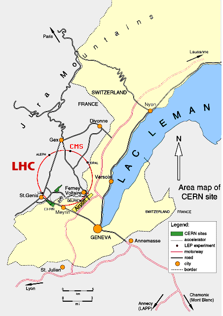
LHC map

blue_ball.gif Because of the very large number of particles which will be produced in the collision of the protons, the CMS detector is designed especially for the identification and measurement of muons. By putting in a large amount of material in the detector, all particles except the muons can then be filtered out, making for easier identification, even under the worst background conditions. Because of the very high center-of-mass energy of the accelerator, many of these muons will be boosted along the beam direction and will therefore strike the endcap regions of

the detector. The endcap muon system (EMU) is one of the two main parts of the detector which are primarily the responsibility of the U.S. institutions participating in the CMS collaboration. It is composed of 3 stations of cathode-strip proportional chambers, interspersed with large disks of steel. The steel disks serve as flux return plates for the 4 T superconducting solenoidal magnet of the CMS detector, and also provide the material needed for filtering out all particles except muons from the system (CMS side view).

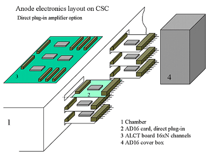
Boards on CSC layout

blue_ball.gif The cathode-strip chambers are trapezoidal in shape, with the cathode strips running radially outwards from the beam line and the anode wires running azimuthally. Each chamber has 6 layers of strips and wires, for redundancy (CSC picture). The largest chambers are 3.4 m long and 1.5 m wide. There are a total of about 500 chambers in the two endcap muon detectors. As a muon traverses a chamber, it ionizes the gas inside the chamber. These ions produce an electrical signal on the cathode strips and on the anode wires. By measuring the charge on each cathode strip, we can measure the position where the muon crossed that layer to within about 100 microns. By following the trajectory of the muon as it curves in the solenoidal magnetic field, we can measure the transverse momentum of the muon with respect to the beam direction. The anode wires are connected together in groups ranging from 5 to 17 wires. By measuring which wire group was hit by a muon we can obtain two crucial pieces of information about the muon: (a) what angle the muon had with respect to the beam direction. This allows us to convert its transverse momentum to a total momentum. (b) which proton-proton beam interaction the muon came from. The two beams collide with each other every 25 ns and there are typically 10-20 interactions every beam crossing. So it is crucial to know which interaction the muon came from. The signals on the anode wires are quite sharp in time and by measuring the time very accurately, we can determine which beam crossing the muon came from. These are the largest cathode-strip chambers ever built and, with over 2 million wires, by far the largest system ever designed. It is also the first time that precision information from both the cathode strips and the anode wires is to be obtained from a cathode-strip chamber.

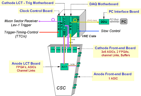
blue_ball.gif The Carnegie Mellon group is responsible for the front-end electronics for the anode wires of the endcap muon system. This involves over 160,000 channels of electronics. We are building custom-designed preamplifier/shaper/discriminator integrated circuits for this purpose. The block diagram of the electronics is shown here. The requirements of the electronics are very low noise, allowing a threshold of about 10-20 fC on the chamber and very good time resolution (time slewing of less than 3 ns for signals from 50 to 1000 fC). Using the 6 layers of a chamber, we want to be able to identify the correct beam crossing for a muon with greater than 92% efficiency. By time-ordering the up to 6 signals from a chamber and using, for example, the second earliest time as an indication of which beam crossing the muon came from, we have obtained time resolutions of about 5-6 ns rms. This time resolution results in a beam crossing efficiency easily above the 92% requirement. The preamp chips each contain 16 channels of input. The chips sit on specially designed boards, which plug directly into the side of the chamber and contain one chip per board ( Boards on CSC layout ). The rest of this web site contains detailed information about the design and present status of the chips and boards, the calibration of the electronics, and results of prototypes from cosmic ray and test beam runs.

Boards on CSC layout

Thomas Ferguson
Department of Physics
Carnegie Mellon University
Pittsburgh, PA 15213

ferguson@cmphys.phys.cmu.edu

Back to EMU CMU home page .
Last modified: Fri Apr 13 14:00:00 CST 2001 teren@fnal.gov